Bartz Equation
The bartz equation is a semi-empirical correlation for predicting the convective heat transfer coefficient along the length of a rocket engine thrust chamber. The heat transfer coefficient influences how much heat will transfer from the hot combustion gas to the solid walls of the thrust chamber. This is sometimes called the gas-side heat transfer coefficient or hotwall heat transfer coefficient and heat transfer coefficient is sometimes abbreviated to “htc“.
The equation was originally proposed by D. R. Bartz in a 1957 technical note “A Simple Equation for Rapid Estimation of Rocket Nozzle Convective Heat Transfer Coefficients“.
Excerpt from Huzel/Huang showing equation for heat flux as a function of HTC and temperature differential:
Correction factor formula with example for gamma=1.2
Note that increasing Mach number decreases HTC and increasing the ratio of wall temperature to gas temperature decreases HTC.
Bartz provided equations for estimating Prandtl number and viscosity when empirical data are not available:
Annotated Bartz Equation with SI Units:
Space Shuttle Main Engine (SSME) Example:
1) First step was to run CEA using the engine operating conditions. This gives me the info needed on the combustion gas properties.
3) Gas properties not directly calculated by CEA can be found using approximations from literature or calculated using reference tables of pure substances and taking a weighted average based on mass fraction.
2) next I created a table of approximate radius vs length of the engine contour using public dimensions/resources on the engine. I was suprised how high the expansion ratio actually is. The TCA is super small compared to the nozzle, the plumbing and turbomachines cover it up and make it look bigger than it is.
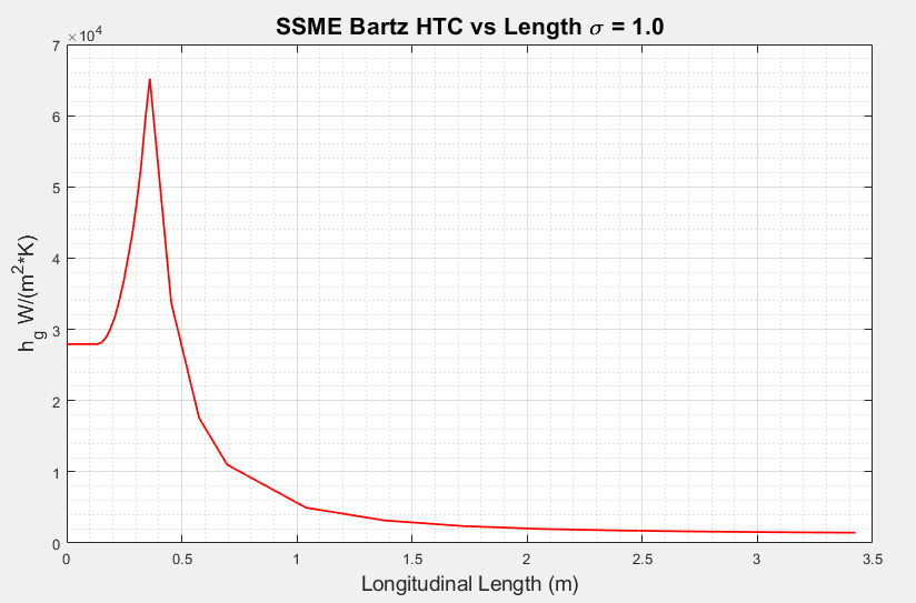
4) Using the tabulated radius we can create a table of flow area vs length. When all the stagnation properties are known, compute htc for each area station. For this simple demonstration I set the correction factor equal to 1.0. I made up a plausible radius of curvature of the throat to be 1”.
The HTC is largest in the combustion chamber and particularly at the throat where it reaches about 65000 W/m^2K. Bartz noted that the dominant factor in determining HTC was mass flow rate per area. As a result, HTC is nearly proportional to density and flow velocity. At the throat, the gas is dense and moving fast which explains why HTC is so high in that location. On the other hand, in the chamber the gas is dense but slow and in the nozzle it’s fast but extremely low density which explains why HTC is lower in those areas of the engine.
If we assume 90% of stagnation temperature is recovered at the wall and the average wall temperature is 650K, we can estimate the heat flux along the engine. When focusing on the throat, we can easily compare our calculation to the real heat flux model of the SSME.


